Assignment 2: I2C and motor control
Prerequisites
Development & debugging environment (follow the setup guide)
Datasheet of the encoder (AS5600)
Introduction
This assignment consists of three parts:
Communicating with the encoder using I2C instead of the ADC
Implementing PWM functions for motor control
Creating your own SmartKnob with haptic feedback
Please use the libraries from the Pico SDK for this assignment - you should not directly write/read to the registers
The SmartKnob is a haptic feedback rotary input, which uses a brushless motor to create software-defined snap points and maxima. The original version by Scott Bezek also features a round touch display to display values, endpoints and snap points.
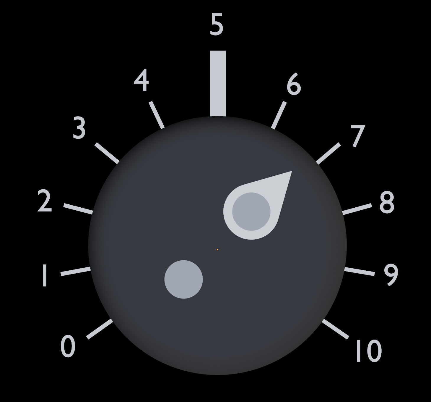
Your task in this assignment is to implement the haptic feedback input with two endpoints and 9 snap points in between. The knob should be used to dim the LED of the Pico in 10% steps. You are not allowed to copy/use code from any SmartKnob implementation on the internet.

The image above shows a possible layout of the 11 snap points with 25-degree spacing between each snap point, the 50% position is aligned with the marker on the board. Feel free to slightly alter (22 - 28 degrees) the angle between the snap points if the haptic feedback feels better with a bit smaller or larger angle.
I2C functions
Implement the following functions for initializing the I2C interface and reading or writing from/to slaves in i2c.c:
Initializes the I2C-0 interface and configures the pins for SDA and SCL. The interface is provided as I2C_INTERFACE, defines for the SDA and SCL pins are also provided.
Checks if the device with the given I2C address is connected to the bus by trying to address the device and checking for an acknowledge (ACK). The function should return 1 if the device was detected, 0 if it did not respond.
Writes a byte (8 bit) into the specified register of the I2C device. Check if the provided address is in the valid I2C-addresses range. A write into a register is done by first sending (I2C write) the register address, then the value.
Writes a word (16 bit) into the specified register of the I2C device. Check if the provided address is in the valid I2C-addresses range. The first byte written is the high byte, the second byte written is the low byte.
Reads a byte (8 bit) from the specified register of the I2C device. Check if the provided address is in the valid I2C-addresses range. A register read is done by first writing the register address, then triggering a read.
Reads a word (16 bit) from the specified register of the I2C device. Check if the provided address is in the valid I2C-addresses range. The first byte read is the high byte, the second byte read is the low byte.
Encoder driver
Next, you will have to implement a small device driver for reading and configuring the encoder using the I2C function from above. The encoder used on the student hardware is an AS5600 (Datasheet).
We expect you to look through the datasheet to identify the correct register bits and addresses for the following functions which you will have to implement in encoder.c:
Initializes the encoder by setting the slow filter mode. Valid values for the slow filter are 2 = 2x, 4 = 4x, 8 = 8x, 16 = 16x. The slow filter of the encoder is used to slow down the reaction speed to sudden changes and noisy readings.
Reads the raw 12-bit rotation value of the encoder from the RAW ANGLE register.
Sets the zero value of the encoder to the given value by writing the zero position into the matching register in the encoder.
Reads the zero-corrected rotation value (0 - 360 degrees) of the encoder by using the ANGLE register.
PWM and motor functions
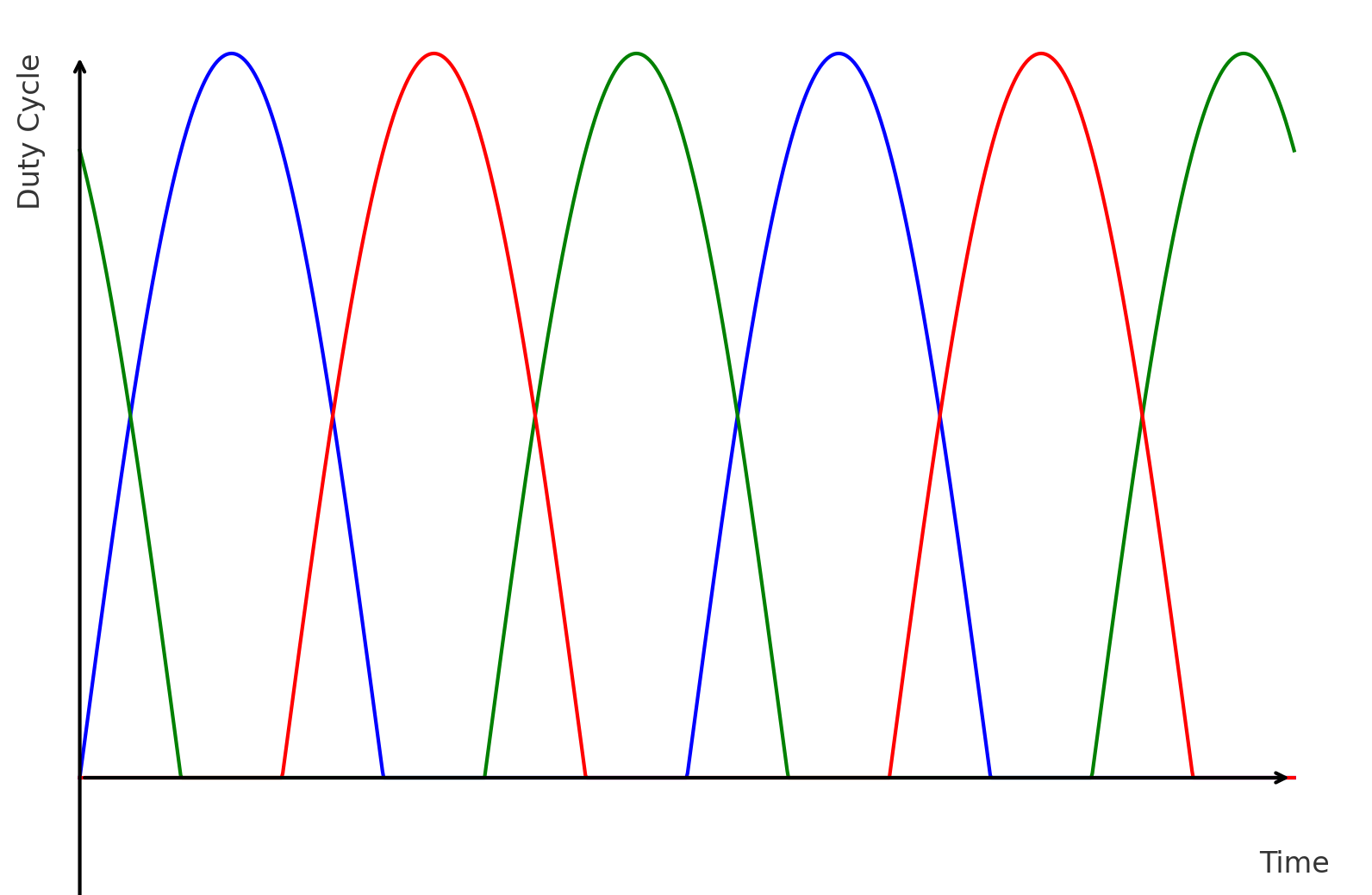
The brushless DC motor is controlled using a SimpleFOC mini motor driver which is connected to the Pico. You will need to output a 3-phase half-wave sine with a phase shift of 120 degrees between each channel that should look like this: 
Channel 1 should have a phase offset of 0 degrees, channel 2 has 120 degrees, and channel 3 has 240 degrees.
The amplitude of the sine function is the duty cycle of the channel, so make sure that the amplitude of the sine functions equals the maximum duty cycle to prevent flat-top sine waves.
Furthermore, you will need drive the enable pin (EN) of the SimpleFOC high to enable the motor. Have a look at the circuit diagram for the pin mappings.
You will have to implement the following functions in pwm.c to initialize and update the PWM hardware:
Initializes all three motor-channel pins for PWM usage and enables the pwm output for all three simultaneously. The duty cycle of the pwm signals should be set to 0. pwm.h provides defines for the channels and a default PWM frequency. The wrap value should be stored in the motor_pwm_wrap variable (global variable in pwm.c). Your implementation should be able to work for any frequency between 1kHz and 40 kHz, you will need to set a clock divider. Note: the Pico only accepts clock dividers between 1.0f and 256.0f.
Initializes the LED pin for PWM usage and enables the pwm output. The duty cycle of the pwm signal should be set to 0. The wrap value should be stored in the led_pwm_wrap variable (global variable in pwm.c).
Sets the duty cycle of the LED pin to the given value. Use the wrap value stored in led_pwm_wrap for your duty cycle calculations. It is okay to have a tiny error for the actual duty cycle due to integer limitations. The MAX_DUTY_CYCLE is not relevant for the LED.
Initializes the enable pin for the motor driver as an output (do not configure it as PWM) and sets the pin to low.
Sets the level of the enable pin to the given value. 1 for high, 0 for low.
Sets the duty cycle of the pwm signal for the given channel. Use 1 for channel 1, 2 for channel 2 and 3 for channel 3. Ensure that the duty cycle is between 0 and MAX_DUTY_CYCLE percent.
Sets the duty cycle of all three pins so that a 3-phase signal is generated with the given angle and amplitude. The angle describes the phase shift of all three sine waves, not the motor. The amplitude should be between 0.0 and 1.0, where 1.0 results in a duty cycle of MAX_DUTY_CYCLE.
Sets the angle of the motor to the given value by rotating the three phases according to the seven pole pairs inside the motor. In this function, the parameter angle refers to the actual rotation of the motor, amplitude should have the same effect as in set_3phase_pwm(...) To complete one rotation, the motor has to pass through all seven poles. You should not implement a feedback loop in this function, just set convert the given angle into the right value for set_3phase_pwm. The feedback loop should be implemented in smart_knob.c
Your task
Implement all basic functions in i2c.c, encoder.c and pwm.c. Have a look at the linked data sheets and circuit diagram for information about registers and pin connections.
Using the functions above, you will have to turn your motor and encoder into a smart knob which dims the LED in 10 percent steps. You have to define two endpoints (0% and 100%) and 9 snap points in between (10%, 20%, ...) with equal spacing. The motor should resist being turned into the dead zone between the two endpoints. Furthermore, the motor should be used to slightly accelerate towards the next snap point to provide haptic feedback. Make sure that the motor is not overcorrecting or blocking on the snap points, just disable the motor when the angle matches the snap point.
Keep in mind that the actual angle of the motor does not match the angle output of the encoder! The pole pairs of the motor might not align with the 0 degree value of the angle, therefore you will need to find and apply this offset. The angle provided to the set_motor_angle function should be translated into the rotation needed for the 7 pole pairs inside the motor. The value does not directly correspond to the angle of the motor like when using a servo motor.
Your code should automatically rotate the motor to the 0% position (~235 degrees relative to the white mark) on startup.
To implement the SmartKnob, you will need to build a feedback loop by reading the rotation from the encoder via I2C and then creating the right magnetic field so that the motor moves towards the given angle. It is sufficient to just implement a proportional controller ("P-Regler") for this assignment, however feel free to implement a better control algorithm such as PID.
The value entered with the SmartKnob should be used to set the PWM duty cycle for the LED on the Pico. Make sure that only the ten-percent step values are used, any value between should result in the closest step value (i.e. 43% => 40%).
Deliverables
i2c.candi2c.hencoder.candencoder.hpwm.candpwm.hsmart_knob.candsmart_knob.h... do not forget to tag the final commit with
SUBMISSION-A2and push the tag
Interview questions
Describe the I2C bus architecture.
Describe how two devices communicate on the I2C bus.
Describe what PWM is and why it can be used to dim a LED.
What resolution has the PWM controller used in the Pico?
What is the benefit of using the slow filter of the encoder instead of averaging values on the Pico?
Why should the PWM of the three phases be enabled simultaneously? Hint: think about the output signal.
How is reading a register of the encoder performed? What I2C communications are necessary?
Briefly describe how a brushless DC motor is controlled.
Why do we need to use a motor driver for controlling the BLDC motor?