Student hardware

The hardware provided consists of the following components:
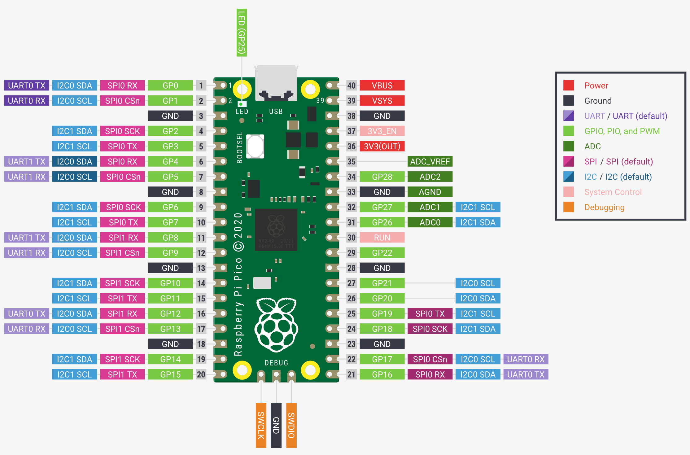
Raspberry PI Pico
A brushless motor with an encoder
Two switches
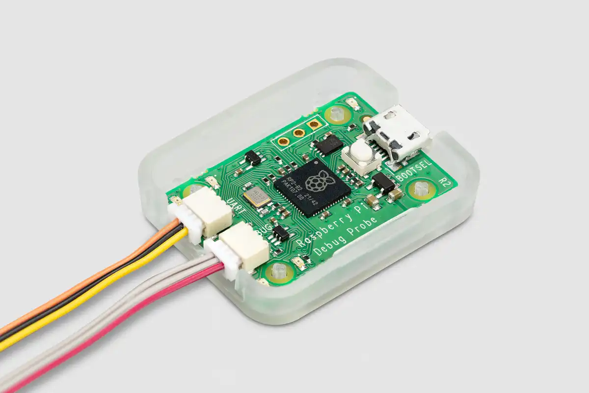
Raspberry PI Debug probe
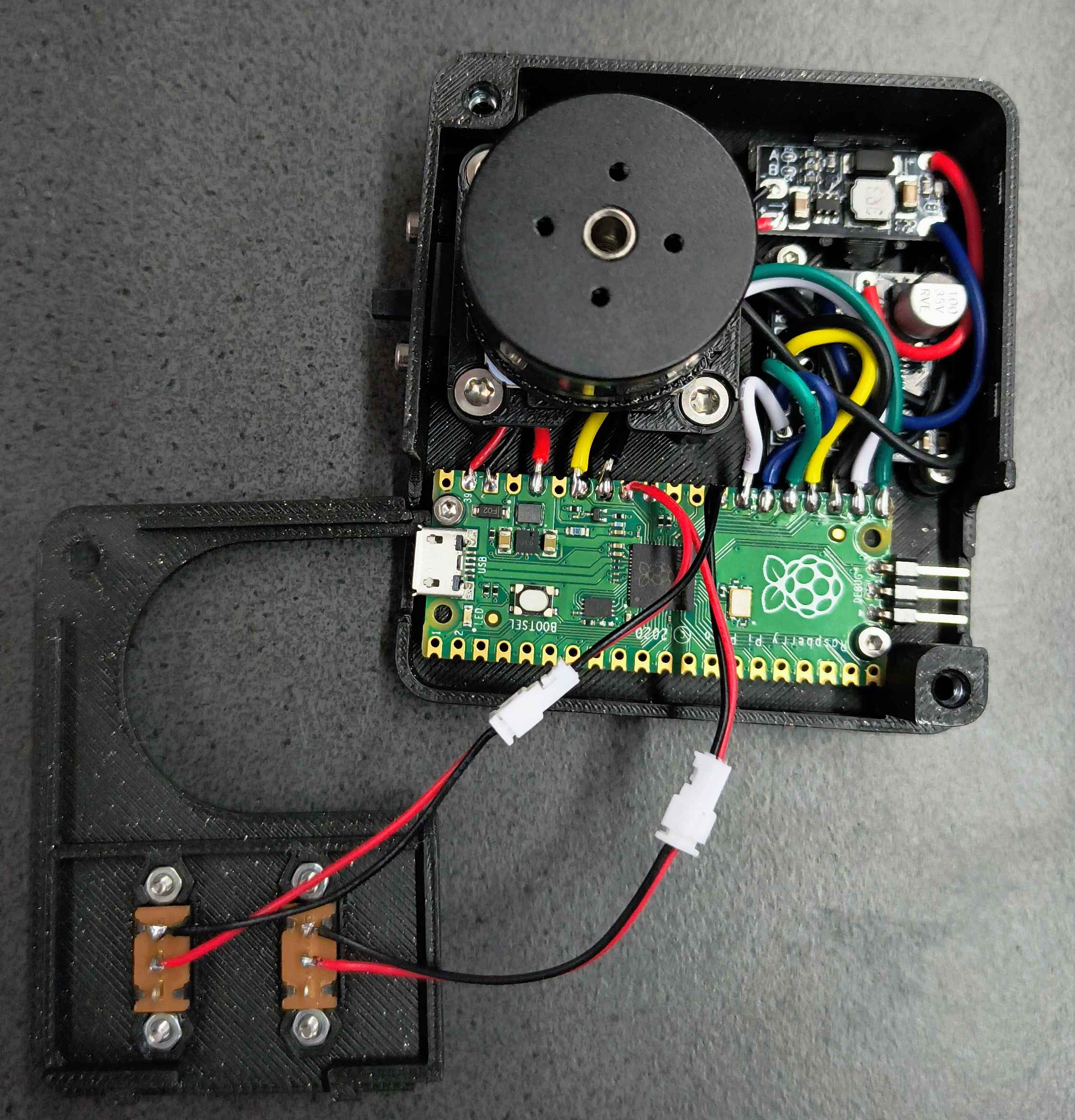
Here is a picture of a partially assembled student board: 
Raspberry PI Pico (RP2040)
The student hardware is based on a Raspberry PI Pico, a microcontroller designed by the Raspberry PI Foundation. Its key features include: Dual-core Arm Cortex M0+ processor, running up to 133 MHz
264KB of SRAM, and 2MB of on-board flash memory
USB 1.1 with device and host support
26 multi-function GPIO pins
2 SPI, 2 I2C, 2 UART, 3 12-bit ADC, 16 controllable PWM channels
Accurate clock and timer on-chip
Temperature sensor
8 Programmable I/O (PIO) state machines for custom peripheral support
An on-board LED

Raspberry PI Debug probe
The debug probe allows debugging the RP2040 microcontroller on the Raspberry PI Pico. The chip is controlled by another RP2040 inside the debug probe, which can control the target using the SWD interface. Furthermore, it is capable of communicating with the Pico using UART. Instructions for connecting the debug probe are provided here. 
Motor with driver and encoder
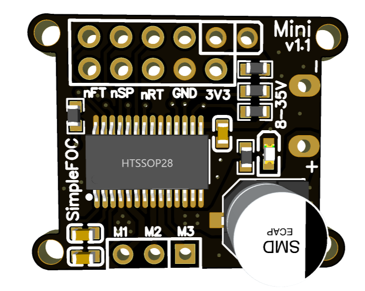
The hardware features a brushless DC Motor which is controlled by a SimpleFOC mini motor driver. This driver is based on the DRV8313 motor driver IC, designed by Texas Instruments. Since the Raspberry PI Pico is only supplied with 5 V, a small boost converter is used to supply the motor driver with 12 V. This also limits the maximal current for the motor to prevent damage.

Below the motor is also a small magnet which used by the encoder to determine the current rotation. The encoder is using an AS5600 IC designed by AMS Osram. It is capable of outputting the current rotation as an analog value using a internal 12-bit DAC. Furthermore, it can be accessed using the I2C bus of the Raspberry PI Pico, the default slave address is 0x36.
Circuit diagram
